Heat engine cutaway in 3D
Connect a working gas, piston, flywheel and energy transfers. Explore the 3D model, inspect its parts and learn with guided explanations. Free on Atlas.
What you can learn
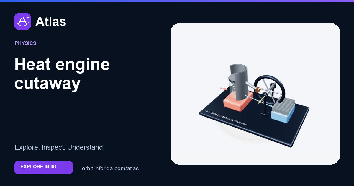
Connect a working gas, piston, flywheel and energy transfers.
Find the moving boundary.
Trace force into the crank.
Distinguish torque from stored rotation.
Try an investigation
Find the moving boundary. Then compare piston assembly with crank and flywheel. Explain what the visible structures show and what the model leaves out.
Check your understanding
What forms the moving gas boundary?
The piston face. The piston face. The transparent gas region ends at the piston face. Gold dots mark a sample of the working substance schematically; they are not a molecule count. Expansion can transfer work through that moving boundary to a load.
What does the flywheel store?
Rotational kinetic energy. Rotational kinetic energy. The shaft carries torque while the flywheel stores rotational kinetic energy. Its mass is concentrated near the rim in this illustration. A flywheel can smooth speed variation but cannot provide unlimited work without an energy input.
A cyclic engine’s absorbed heat becomes…
Work plus rejected heat. Work plus rejected heat. Over a complete cycle, absorbed heat is divided between net work and rejected heat. The red, gold and blue arrows identify those transfers. They are not material tubes or a live temperature map of the apparatus.
Sources and model scope
Generic piston heat-engine exhibit, not a complete operating engine design. Reservoir arrows describe a whole cycle; valves and cycle timing are not simulated.