Electric circuits in 3D
Trace a series–parallel circuit and place measuring instruments. Explore the 3D model, inspect its parts and learn with guided explanations. Free on Atlas.
What you can learn
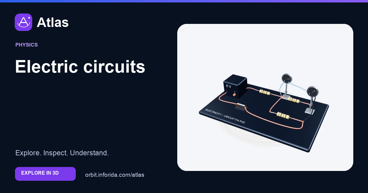
Trace a series–parallel circuit and place measuring instruments.
Find the shared route.
Find the same two nodes.
Break the return path mentally.
Try an investigation
Find the shared route. Then compare parallel branches with switch. Explain what the visible structures show and what the model leaves out.
Check your understanding
R2 and R3 are parallel because…
They connect to the same two nodes. They connect to the same two nodes. R2 and R3 connect across the same pair of junctions. They share a potential difference, while the total current divides between them. Their apparent front-to-back separation does not decide whether they are series or parallel.
An ammeter is normally inserted…
In series with the measured branch. In series with the measured branch. The ammeter is inserted into the upper branch, with no wire directly bypassing it. It samples that branch’s current. Placing a current meter directly across a supply would be a different and inappropriate connection.
An ideal voltmeter draws…
No current. No current. The blue leads span the two ends of the parallel resistor combination. An ideal voltmeter draws no current while comparing potential. Both instrument needles are illustrative, not computed readings for chosen component values.
Sources and model scope
Static low-voltage teaching circuit: R1 in series with R2 parallel to R3. Meter needles are illustrative. No live circuit simulation or component ratings are provided.